
The 14-Step Site Preparation & Foundation Readiness Sequence
From utility notification through the final foundation-readiness check, this ground-up sequence prepares the site, manages drainage and moisture, establishes the structural floor system, and confirms that the completed platform is stable, square, properly supported, and ready before exterior wall framing begins.
Built In Order, Verified At Every Layer
A dependable backyard structure starts before the walls are framed. The process below moves from underground-utility awareness and site clearing through layout, excavation, subgrade preparation, drainage layers, moisture protection, foundation beams, floor framing, structural plywood, and a final system-wide readiness inspection.
Follow the sequence in order. Each stage identifies what is being completed, the construction logic behind it, and the field conditions that should be verified before the next layer is added.
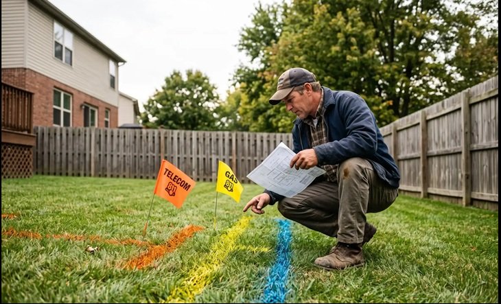
Underground Utility Notification — 811 Call Before You Dig
What Happens
Before excavation, stake driving, grading, or equipment placement begins, the underground-utility locate process must be completed. Registered utility operators identify applicable buried infrastructure with standardized markings so the work area can be approached safely.
Public utility locating does not necessarily identify every homeowner-installed or privately owned underground system. Irrigation, pet fencing, landscape lighting, private electric, septic components, drainage lines, pool utilities, and similar systems should be disclosed before site work begins.
- 811 coordination completed before ground disturbance.
- Required utility-locate waiting periods satisfied.
- Marked utility areas respected during layout and excavation.
- Private underground systems disclosed or investigated separately.
- No unnecessary stake driving or excavation begins before this step is complete.
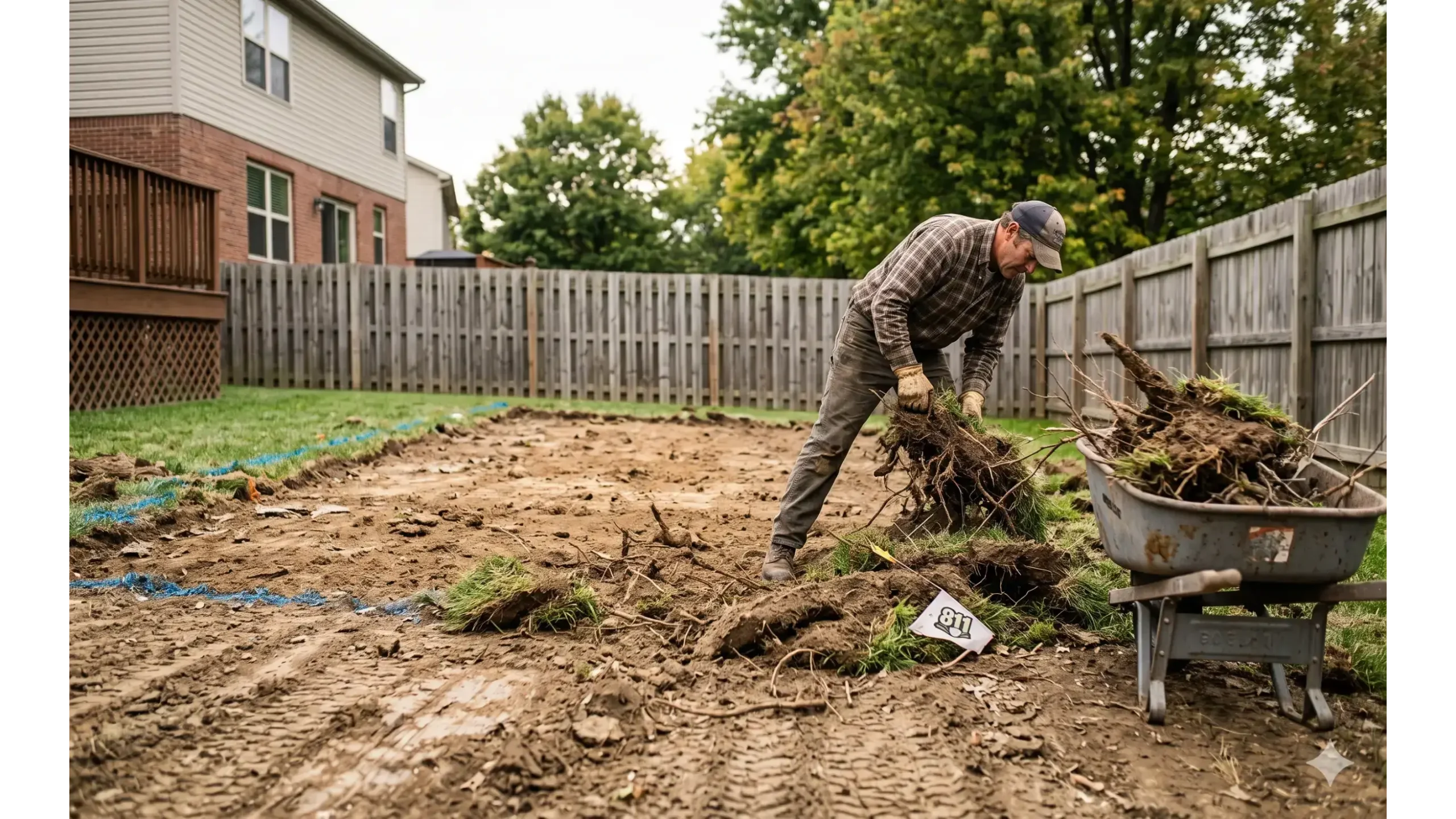
Clear The Site — Remove Organic Material And Obstructions
What Happens
The proposed building area is opened up so the actual ground conditions can be seen and worked. Brush, surface debris, loose material, vegetation, roots, and other obstructions are removed. If an existing shed or small outbuilding occupies the location, demolition and complete removal should occur before foundation preparation begins.
Material that can rot, compress, retain moisture, or interfere with excavation should not simply be buried beneath the new foundation.
- Vegetation, brush, roots, debris, and loose material removed.
- Old structures fully removed where applicable.
- No demolition debris intentionally buried beneath the new pad.
- Access route opened for materials, tools, and equipment.
- Work area cleared sufficiently for accurate layout.
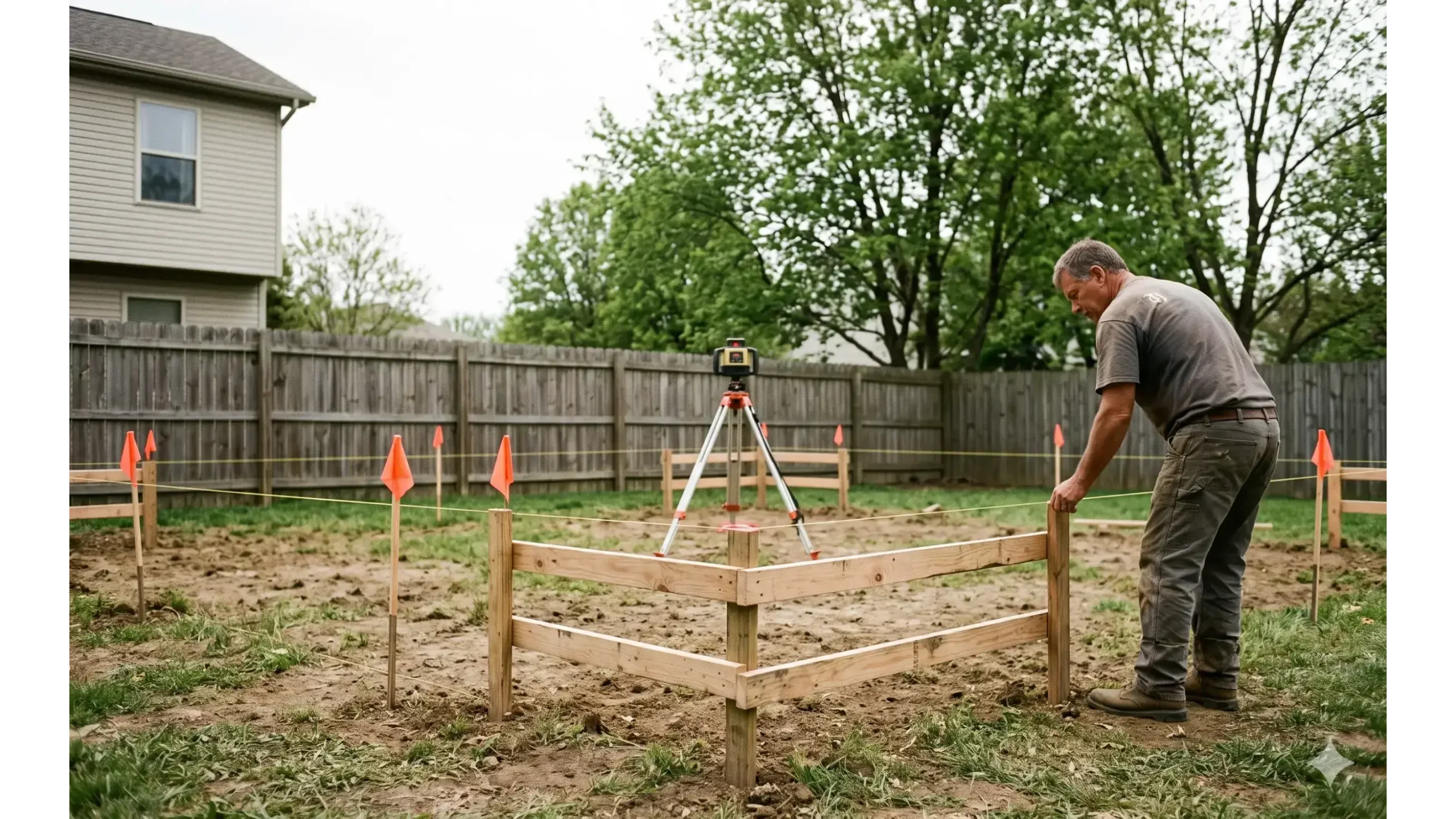
Stakes, Batter Boards & Laser Control — Establish The Reference Before Excavation
What Happens
The prepared-pad boundary and the actual building footprint are established before excavation. For this 10×12 example, the prepared area is planned at a minimum of 14×16 so the drainage base extends beyond the building on all sides.
Stakes, flags, batter boards, string lines, and laser elevation references allow the crew to control building position, squareness, pad limits, and finish-floor elevation even after the original ground surface has been disturbed.
- 10×12 building footprint established.
- 14×16 minimum prepared-pad boundary identified.
- Reference lines maintained outside the excavation zone.
- Finish-floor elevation related to surrounding drainage.
- Laser and string references confirmed before excavation begins.
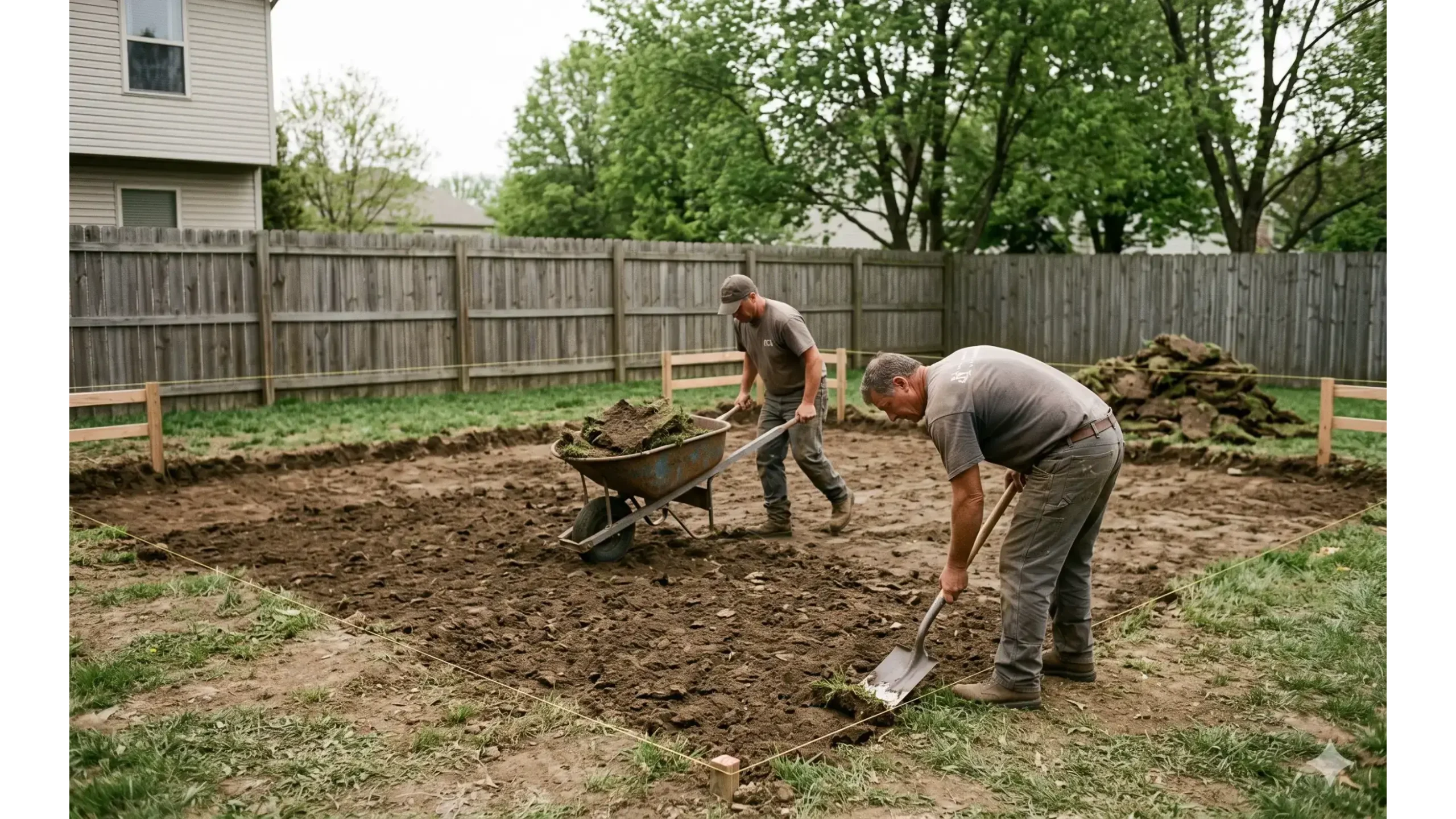
6-Inch Minimum Excavation — Remove Unstable Organic Material
What Happens
Sod, root systems, organic topsoil, loose material, and other biologically active material are excavated from the full prepared pad area. Six inches is used as the minimum example depth, while actual excavation may need to extend farther where soil conditions require reaching a more dependable mineral subgrade.
Clean reusable topsoil may be stockpiled away from the work area for later finish grading, while unsuitable material is kept out of the future foundation system.
- Minimum 6-inch excavation used for the example foundation.
- Sod, roots, stumps, and organic topsoil removed.
- Depth adjusted where actual soil conditions require.
- Clean topsoil stockpiled only where appropriate for later grading.
- Excavation maintained within established layout controls.
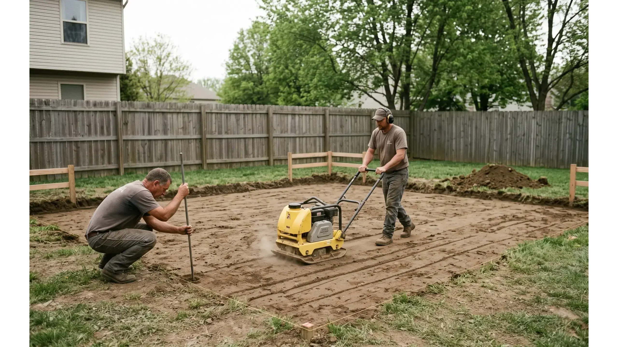
Inspect, Regrade & Compact The Native Subgrade
What Happens
Once excavation exposes the native subgrade, the surface is reviewed for soft areas, loose fill, wet pockets, remaining roots, unstable material, and conditions that could rut or settle. Unsuitable areas are corrected before the drainage base continues.
The prepared soil is then shaped to support positive water movement and compacted in overlapping passes to create a firm, reasonably uniform support layer below the geotextile and stone.
- Soft, wet, loose, or unstable areas identified.
- Unsuitable material removed, replaced, or reworked as needed.
- Subgrade shaped with drainage in mind.
- Plate compactor used in overlapping passes.
- Surface confirmed stable before geotextile installation.
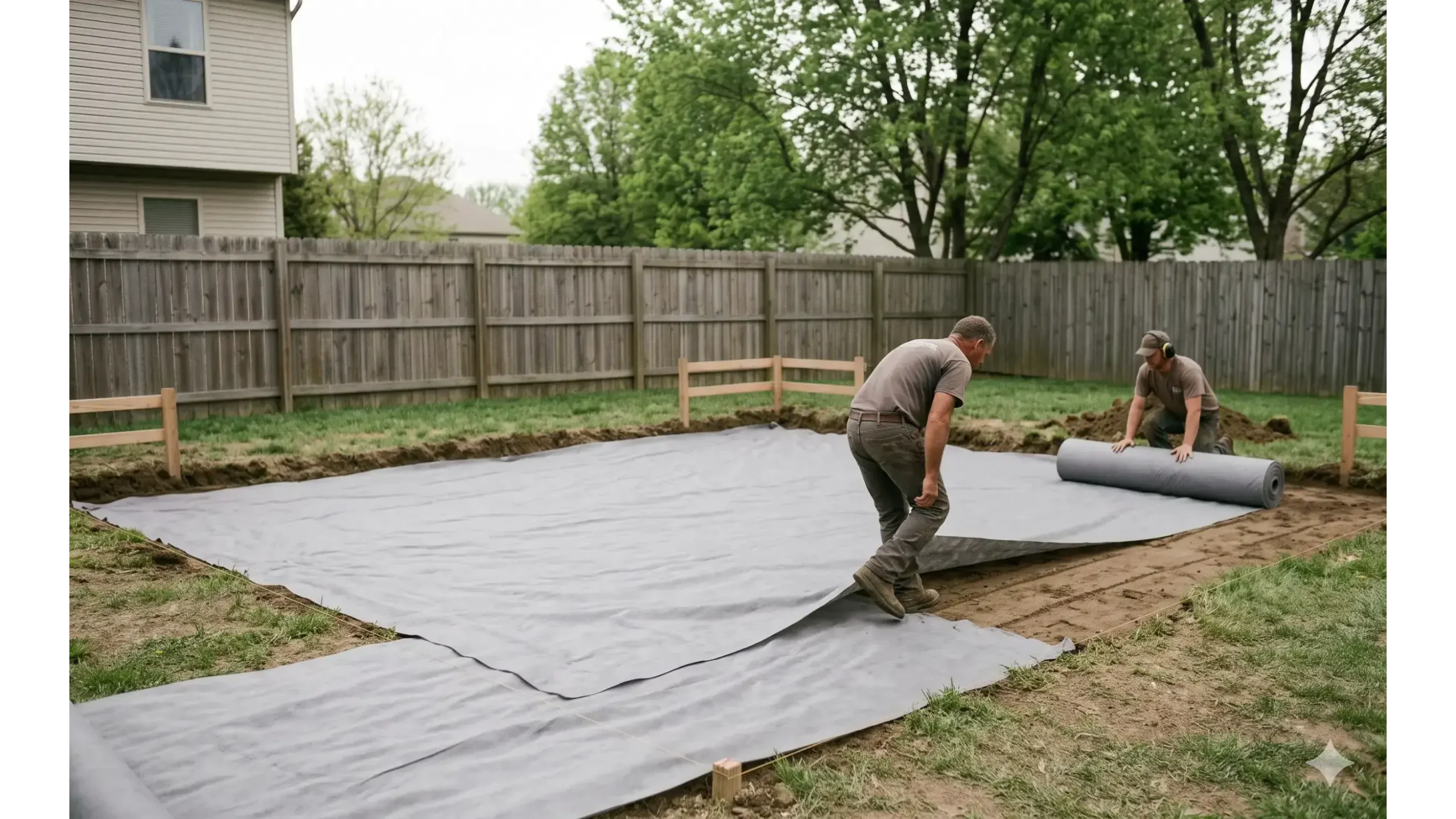
Geotextile Fabric — Keep The Stone Base Separated From The Soil
What Happens
Commercial stabilization fabric is installed directly over the prepared subgrade before any stone is placed. The fabric separates the clean angular stone above from clay, soil, and softened subgrade below.
Where multiple runs are required, seams are overlapped and the material is kept reasonably flat across the prepared pad footprint. This layer is different from the 10-mil moisture barrier installed later above the stone.
- Commercial stabilization fabric over the full prepared area.
- Installed directly over compacted subgrade.
- Seams overlapped where multiple runs are needed.
- Fabric extended to support the complete gravel footprint.
- No clean stone placed directly on exposed clay or organic soil.
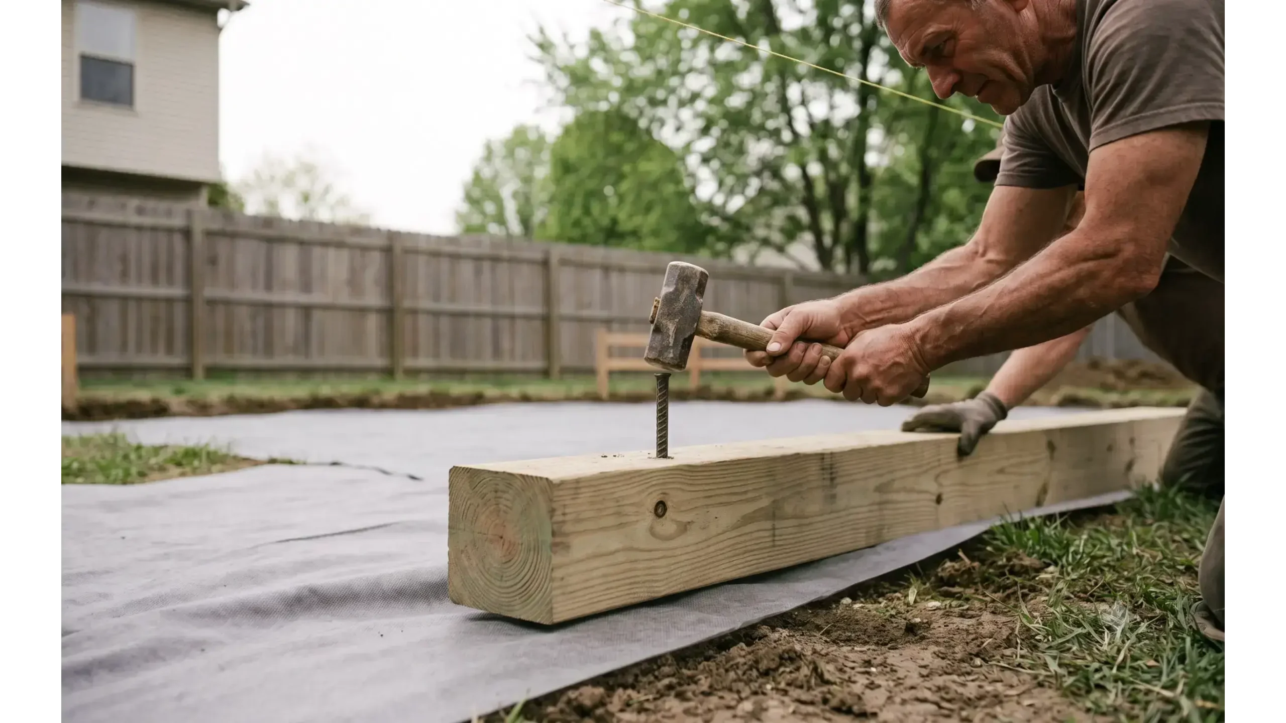
Pressure-Treated Perimeter Containment — Hold The Stone Base In Place
What Happens
Pressure-treated containment timbers define the outside edge of the prepared gravel pad. The perimeter helps keep stone from migrating outward, maintains a cleaner foundation edge, and preserves the intended pad footprint during installation and long-term use.
The containment is checked against the established layout and may be secured with suitable stakes or other restraint where site conditions permit.
- Pressure-treated containment around the prepared pad.
- Boundary checked against the planned layout.
- Containment installed before stone placement.
- Secured appropriately where site conditions permit.
- Finished edge kept aligned and stable.
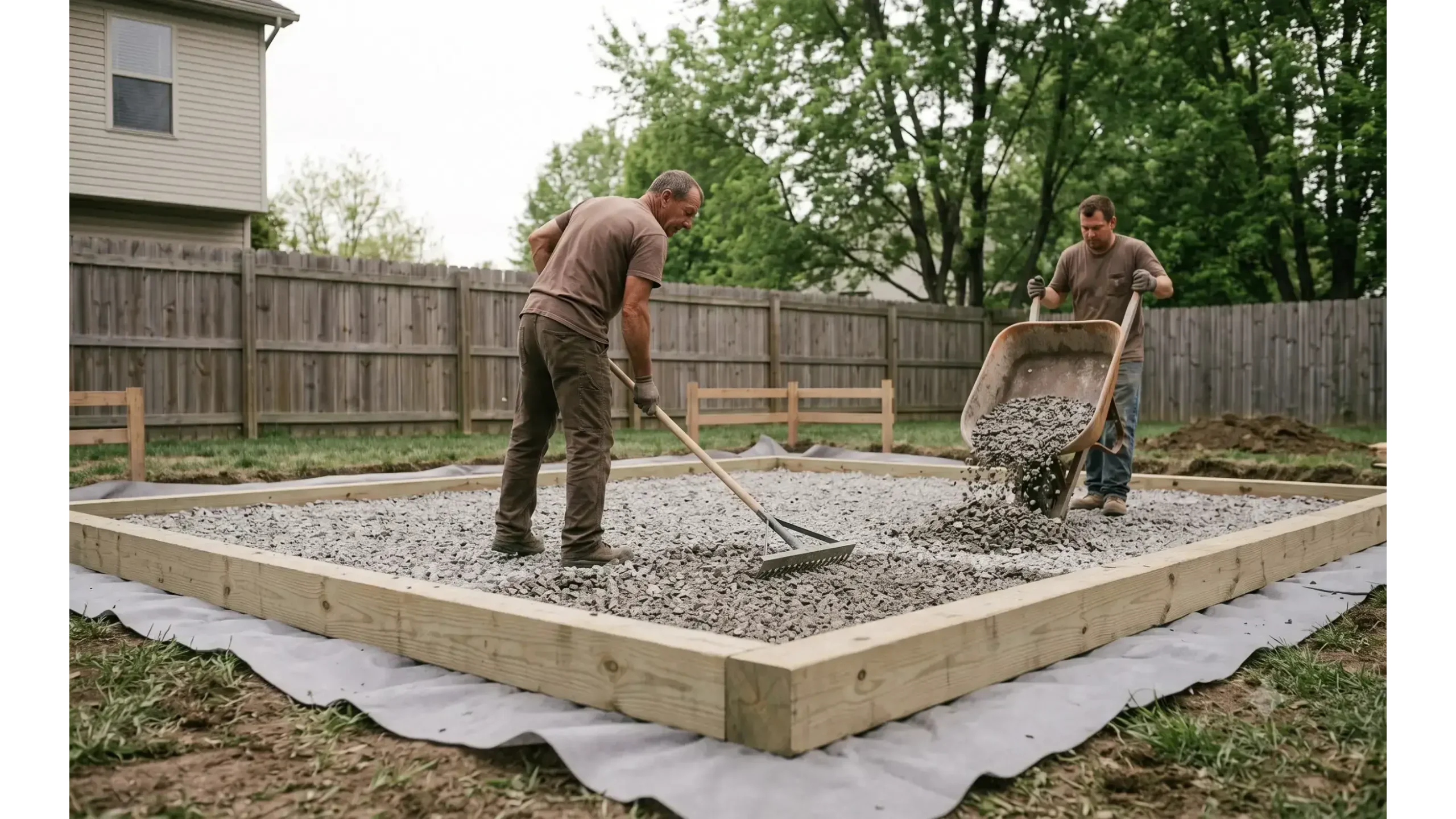
6-Inch #57 Limestone Base — Drainage, Bearing & Stability
What Happens
A minimum six-inch layer of #57 washed limestone, or comparable clean angular stone, is distributed across the prepared pad inside the perimeter containment. The stone is spread over the geotextile layer and brought toward the planned elevation.
Clean angular stone provides a stable, free-draining layer beneath the moisture barrier and structural foundation system. Its open voids allow water to move through the base rather than remaining trapped directly against the wood structure.
- Minimum 6-inch clean angular stone base.
- #57 washed limestone or comparable material.
- Stone placed over geotextile fabric.
- Base distributed across the complete prepared pad.
- Pad extension maintained beyond the building footprint.
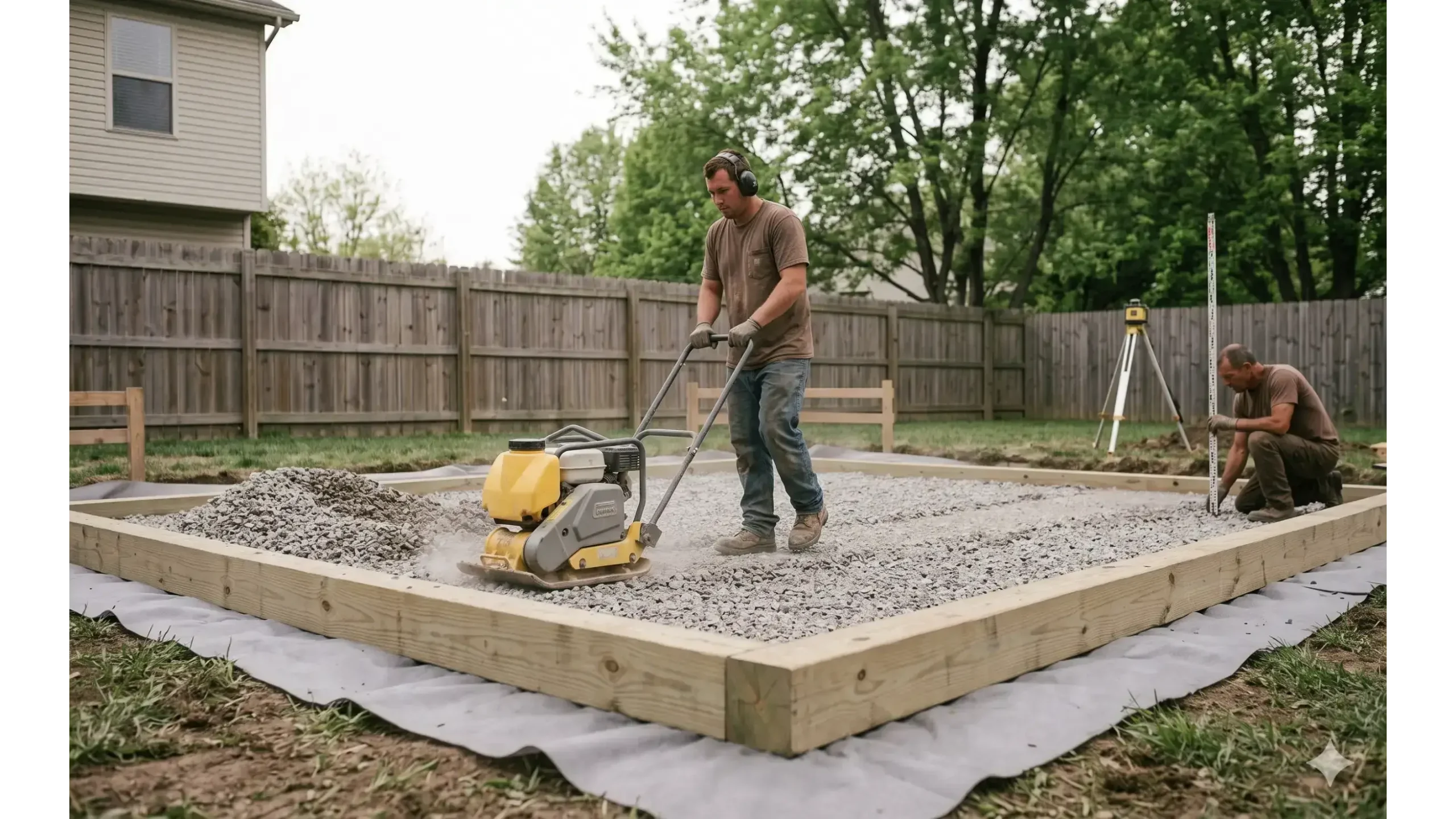
Level, Seat & Consolidate The Stone Before Moisture Protection Begins
What Happens
The stone base is adjusted across the full pad so high areas are corrected, low areas are filled, and the final surface conforms to the intended elevation. Clean #57 stone is seated and consolidated rather than treated exactly like compacted soil or dense crusher fines.
The goal is an even, stable drainage base that will not rock or shift excessively when the moisture barrier and structural foundation system are installed above it.
- Stone checked against the planned elevation.
- High spots adjusted and low areas filled.
- Angular stone seated and stabilized.
- Finished base checked for consistent support.
- Moisture barrier not installed until the stone is ready.
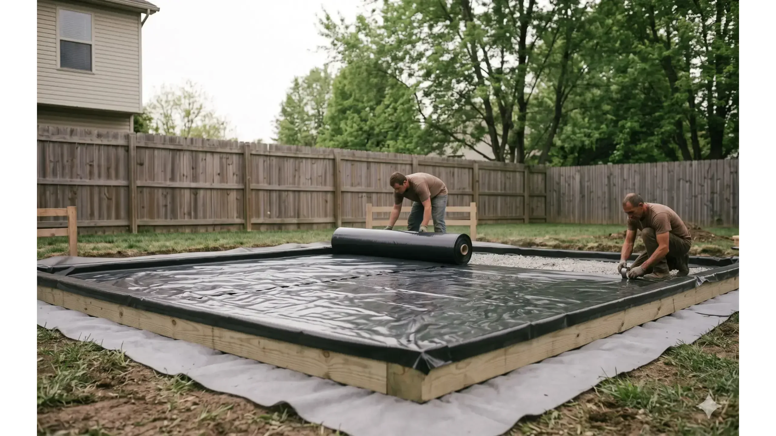
Moisture Barrier Over Stone — Separate The Wood Foundation From Ground Moisture
What Happens
A 10-mil polyethylene moisture barrier is placed over the finished stone base before the structural foundation beams are installed. The material is laid flat, and where more than one sheet is required, seams are overlapped and secured.
This membrane is a different layer from the geotextile beneath the gravel. The geotextile separates soil and stone; the upper polyethylene layer provides additional moisture separation beneath the wood foundation and floor system.
- 10-mil polyethylene installed above finished stone.
- Placed before foundation beams are installed.
- Sheets laid flat across the prepared footprint.
- Seams overlapped and secured where required.
- Membrane protected from avoidable punctures during framing.
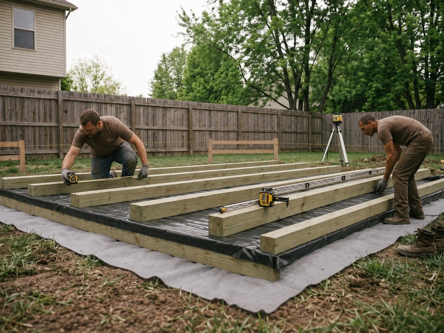
6×6 Ground-Contact Foundation Beams — The Structural Base That Carries The Floor
What Happens
Ground-contact pressure-treated 6×6 foundation beams are positioned over the moisture-protected stone pad and aligned with the actual 10×12 building footprint. The beams run in the 12-foot direction and are distributed across the width to provide stable structural bearing beneath the floor framing.
Each beam is checked for straightness, spacing, alignment, and elevation. The completed beam system should form a consistent, co-planar support surface before the floor joists are framed above.
- Ground-contact pressure-treated 6×6 foundation beams.
- Beams positioned above the 10-mil moisture barrier.
- Beam layout aligned to the 10×12 building footprint.
- Supports distributed appropriately across the building width.
- Straightness, spacing, level, and co-planar bearing verified before floor framing.
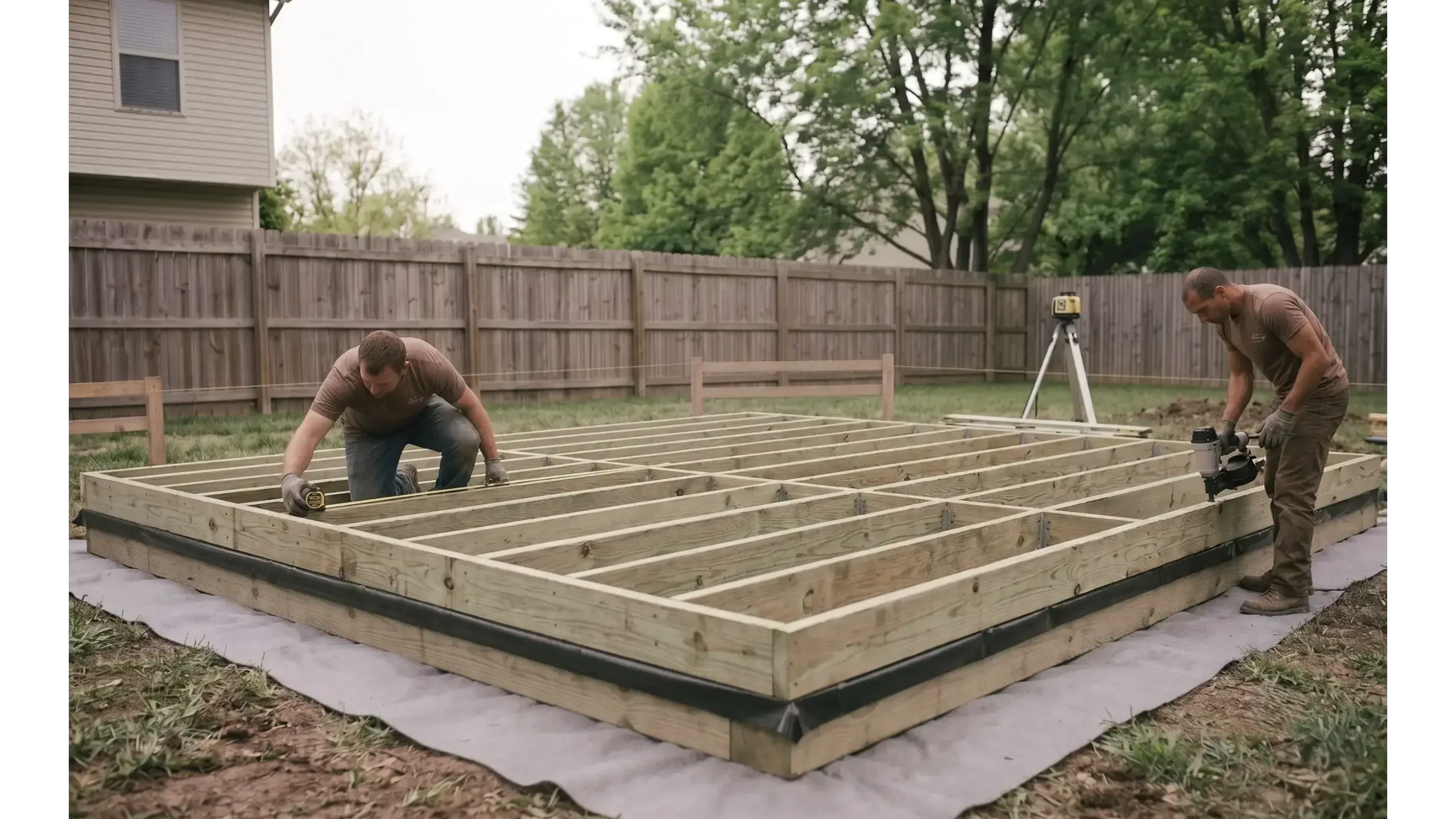
2×6 Pressure-Treated Floor Joists — Framed 16 Inches On Center With Blocking
What Happens
The floor system is framed with pressure-treated 2×6 joists installed at 16 inches on center. The joists run perpendicular to and bear on the 6×6 foundation beams, while rim framing establishes the outside floor perimeter.
Blocking helps control joist movement, maintain consistent spacing, and improve floor stiffness. Before plywood installation, the frame is reviewed for bearing, spacing, alignment, and squareness.
- 2×6 pressure-treated floor joists.
- Joists installed at 16 inches on center.
- Floor frame square to the actual building footprint.
- Rim framing and blocking installed as required.
- Spacing, alignment, bearing, and squareness verified before sheathing.
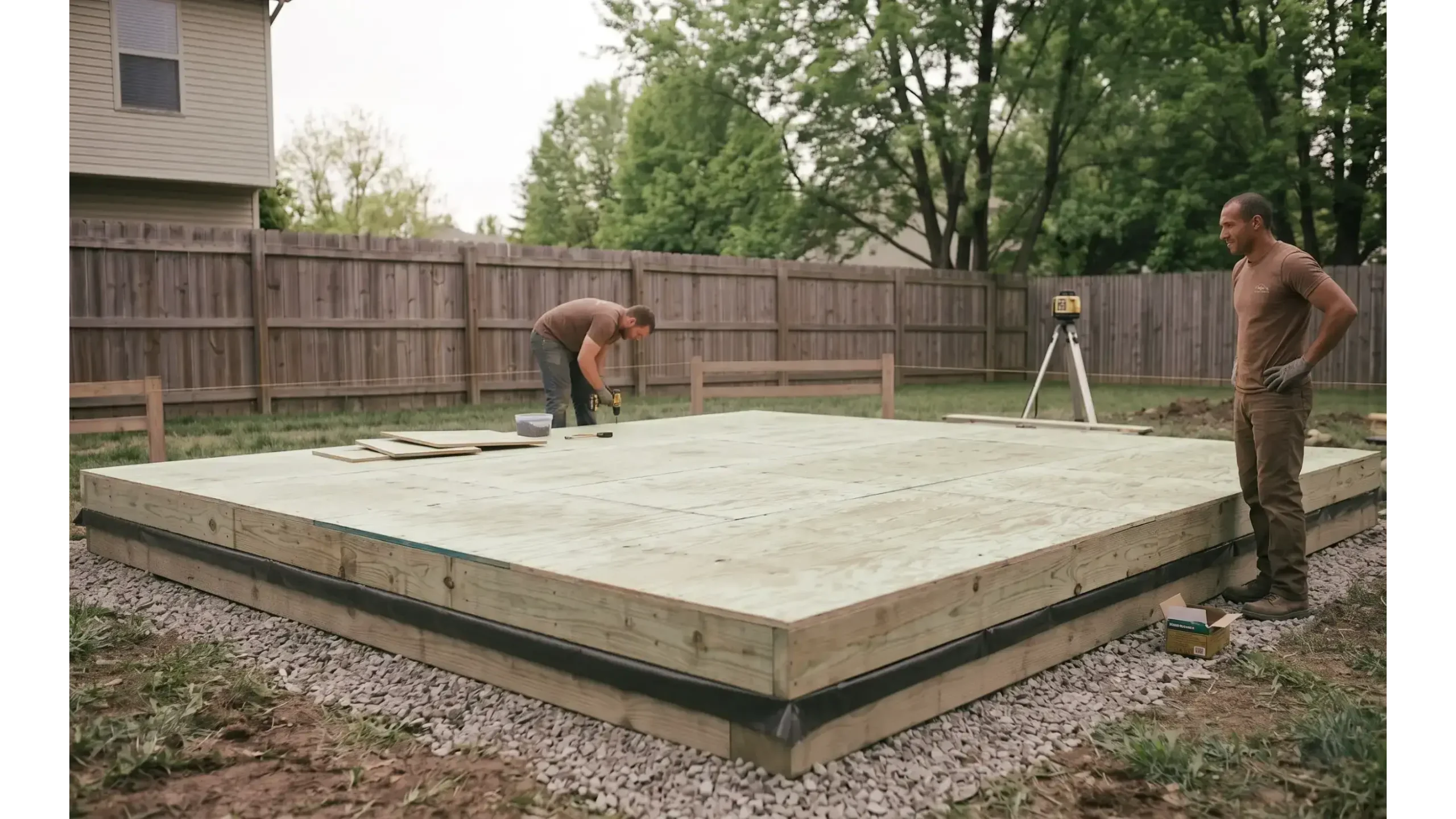
3/4-Inch Pressure-Treated Plywood — Complete The Structural Floor Platform
What Happens
The completed 2×6 floor frame is covered with 3/4-inch pressure-treated plywood. Sheets are laid out and fastened to the joist and rim-framing system so the platform becomes a connected, structural surface for the building above.
By this stage, the layered system includes the prepared subgrade, stabilization fabric, drainage stone, moisture protection, 6×6 foundation beams, 2×6 floor joists, blocking, rim framing, and the structural plywood deck.
- 3/4-inch pressure-treated plywood subfloor.
- Plywood fastened to the 2×6 joists and rim framing.
- Panel layout checked for proper support.
- Platform reviewed for stiffness and squareness.
- Subfloor completed before the final readiness inspection.
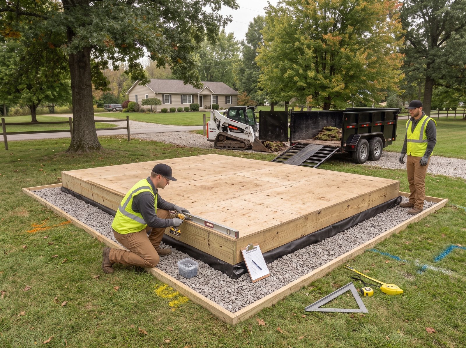
Final Foundation Readiness Check Before Wall Framing Begins
What Happens
Before exterior walls are framed, the completed platform is inspected as one connected foundation and floor system. The review considers plywood fastening, floor stiffness, joist bearing, beam alignment, squareness, level, moisture-control placement, drainage exposure, prepared-pad clearance, and overall work-zone readiness.
This is the transition from foundation work to vertical construction. Each layer has already been examined during installation; Step 14 confirms that those individual layers now function together as a dependable platform.
- Completed platform checked for square, level, and overall stability.
- Plywood fastening and floor-system stiffness reviewed.
- Joist bearing and alignment over the 6×6 beams confirmed.
- Moisture-barrier condition and prepared-pad perimeter reviewed.
- Drainage clearance around the foundation area confirmed.
- Wall framing begins only after the platform is ready as a complete system.
Every Layer Has A Job Before The Walls Go Up
A durable backyard structure is not supported by one material or one shortcut. Site preparation, drainage, soil separation, moisture control, structural bearing, floor framing, subfloor installation, and final verification all contribute to the completed system.
| Layer / Stage | Purpose | Field Standard |
|---|---|---|
| 811 Utility Notification | Identifies applicable underground utility risks before disturbance. | Locate requirements satisfied before excavation or stake driving. |
| Cleared Work Zone | Removes organic material, debris, and physical obstructions. | Foundation area and access route cleared before layout continues. |
| Layout & Elevation | Controls pad location, building footprint, square, and finish elevation. | Stakes, batter boards, strings, and laser references established. |
| Excavated Subgrade | Removes sod, roots, topsoil, and unsuitable organic material. | Minimum 6-inch example excavation; deeper where conditions require. |
| Prepared Subgrade | Creates a firm support surface below the drainage system. | Soft areas corrected and soil compacted in overlapping passes. |
| Geotextile Fabric | Separates clean angular stone from the soil below. | Commercial stabilization fabric installed before stone placement. |
| Perimeter Containment | Defines the stone pad and reduces outward gravel migration. | Pressure-treated containment aligned and secured appropriately. |
| #57 Limestone Base | Provides drainage and a stable angular-stone support layer. | Minimum 6-inch clean stone base across the prepared area. |
| Consolidated Stone | Creates an even and stable surface for the structural layers above. | Stone adjusted, seated, and checked against planned elevation. |
| 10-Mil Moisture Barrier | Adds moisture separation beneath the structural wood foundation. | Installed above finished stone before foundation beams. |
| 6×6 Foundation Beams | Provides primary structural bearing for the floor system. | Ground-contact PT beams aligned, level, evenly distributed, and co-planar. |
| 2×6 Floor Joists | Creates the structural floor grid beneath the plywood deck. | Pressure-treated joists at 16 inches OC with rim framing and blocking. |
| 3/4-Inch PT Subfloor | Completes the structural floor platform. | Pressure-treated plywood securely fastened over the verified frame. |
| Final Readiness Check | Verifies that all foundation and floor components function as one system. | Square, level, bearing, fastening, moisture, drainage, and work-zone conditions reviewed before walls. |
The Foundation Is Not An Afterthought. It Is The First Quality Decision.
Site preparation influences drainage, bearing, moisture exposure, floor performance, access, and the long-term confidence of the structure above. A premium shed, studio, workshop, garden building, pool house, or specialty building should not begin with a shortcut below the floor.
The objective is straightforward: prepare each layer deliberately, verify the structural platform as a complete system, and begin wall framing only after the building has a stable, square, dry, and properly supported starting point.
Plan The Backyard Structure With The Site And Foundation Understood First
The Vintage Shed Company builds premium on-site backyard structures with owner-led planning, clearly defined construction standards, and a foundation-first process designed around the actual property, intended use, access, drainage, and project scope.